
How do centrifugal pumps work?
Centrifugal pumps are dynamic pumps that move fluids through a system using one or more impellers. They are the most common type of pump because of the simplicity and effectiveness of their design and operation. Because they are the most familiar, they also tend to cost less than other types of pumps. Compared to positive displacement pumps, they provide higher flow rates and lower pressures. MPS Pumps have been designed to handle virtually any application where water has to be moved. They've been fulfilling the needs of professionals and consumers for decades with quiet, efficient and reliable 24/7 performance. They feature a magnet impeller assembly and an epoxy encased power unit ensuring that water never gets contaminated with harmful oils or chemicals.
Pump construction
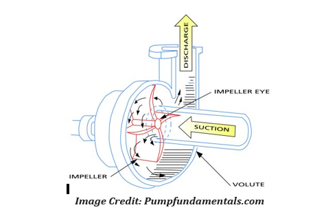
Centrifugal pumps consist of a set of rotating vanes called an impeller. The rotary vanes are typically enclosed within a housing and are used to impart energy to a fluid through centrifugal force. The pump has two main parts: a rotating element that includes an impeller and a shaft, and a stationary element made up of a casing (volute).

Pump operation
Centrifugal pumps operate using kinetic energy to move fluid, utilizing an impeller and a circular pump casing. A vacuum is created in the pump, which draws fluid to the impeller by suction. The impeller produces liquid velocity and the casing forces the liquid to discharge from the pump, converting velocity to pressure. This is accomplished by offsetting the impeller in the casing and by maintaining a close clearance between the impeller and the casing at the cutwater. By forcing fluid through without cupping it, centrifugal pumps can achieve very high flow rates.

Types
Centrifugal pumps generate flow by using one of three actions: radial flow, mixed flow, or axial flow.
-
Radial flow pumps are characterized by high pressure and low flow. They accelerate liquid through the center of the impeller and out along the impeller blades at right angles (radially) to the pump shaft. Pressure is developed wholly by centrifugal force.

Image Credit: Engineer's Edge
- Mixed flow pumps incorporate characteristics from both axial and radial flow pumps, with typically medium flow and medium pressure. They push liquid out away from the pump shaft at an angle greater than 90°. Pressure is developed partly by centrifugal force and partly by the lifting action of the impeller.
Mixed flow impeller:

The image below provides visual example of how liquid might flow through these different types of pumps:

Performance Specifications
Centrifugal pump selection is defined by a few key specifications, including flow rate, head, power, and efficiency.
- Flow rate describes the rate at which the pump can move fluid through the system, typically expressed in gallons per minute (gpm). The rated capacity of a pump must be matched to the flow rate required by the application or system.
- Pressure is a measure of the force per unit area of resistance the pump can handle or overcome, expressed in bar or psi (pounds per square inch). As in all centrifugal pumps, the pressure in axial flow pumps varies based on the pumped fluid's specific gravity. For this reason, head is more commonly used to define pump energy in this way.
- Head is the height above the suction inlet that a pump can lift a fluid. It is a shortcut measurement of system resistance (pressure) which is independent of the fluid's specific gravity, expressed as a column height of water given in feet (ft) or meters (m).
- Net positive suction head (NPSH) is the difference between the pump's inlet stagnation pressure head and the vapor pressure head. The required NPSH is an important parameter in preventing pump cavitation.
- Output power, also called water horsepower, is the power actually delivered to the fluid by the pump, measured in horsepower (hp).
- Input power, also called brake horsepower, is the power that must be supplied to the pump, measured in horsepower (hp).
- Efficiency is the ratio between the input power and output power. It accounts for energy losses in the pump (friction and slip) to describes how much of the input power does useful work.
Features
The pump is a magnetically driven centrifugal water pump. It has no seals to wear and contains no oil. The pump can be used submerged or inline. Inline means connections are made directly to the pump inlet and outlet ports, which have 3/4 " NPT threads. All electrical components are encapsulated in epoxy. The energy used is approximately 1/2 of regular driven pumps. . This helps to give uninterrupted service. INLINE PIPING Centrifugal pumps cannot pull water from a lower level. In order to start, pump must be below water level and filled with water. Unless the air can escape from the outlet, the pump will not start. Do not use glues or solvents to connect the pumps threaded fittings. Use Teflon pipe tape. The pump cover is not designed to support long pipe runs or to correct pipe misalignment.

Service & Maintenance
The pump cover should occasionally be removed to clean and inspect the impeller assembly. The impeller is the only serviceable item and can be pulled out of the body . Do not take the impeller apart. If it is worn or broken the entire impeller assembly should be replaced. This will restore the pump to original capacity. Pumps taken out of service for an extended period with fluid inside run the risk of forming a crust which may prevent subsequent starting. Saltwater should be flushed out with fresh water. Always check cord for sharp bends which can cause premature cracking. Do not use power cord to lift or move pump. Other than Impeller maintenance, this appliance has no user serviceable parts. Magnet impeller assembly must be routinely cleaned to remove accumulations of scale or calcium. This procedure should be done at least once every three months - or more often if the water conditions require it. Salt water and hard water environments require more frequent cleaning.
Materials
Pumps and their various components are made up of a number of different materials. Media type, system requirements, and the surrounding environment all are important factors in material selection.
- Chemical compatibility- Pump parts in contact with the pumped media and addition additives (cleaners, thinning solutions) should be made of chemically compatible materials that will not result in excessive corrosion or contamination.
- Explosion proof- Non-sparking materials are required for operating environments or media with particular susceptibility to catching fire or explosion.
- .
Power Source
MPS Pumps can be driven by a number of different power sources. The most common are electric motors, 120 VAC or 220 VAC.Application Considerations
- Impeller design - While a pump manufacturer usually has the job of selecting or designing a pump's impeller, for certain applications (namely certain media types) the impeller must be specially selected. For example, a grinder type blade/impeller design may be required for handling thick slurries, abrasives, or other solids filled media (see the Grinder Pumps Selection Guide for more information).
-
Inlet and outlet connections - The inlet (suction) and outlet (discharge) openings of the pump must be sized appropriately to fit the requirements of the system. Proper pipe or tube fittings must also be considered to make the proper connections.